


In the transformer power distribution operation, the transformer is indispensable. It is very necessary to familiarize with and master the basic knowledge of the transformer. The basic knowledge reserve of the transformer is a necessary skill for every electric power person!
1. What is a transformer?
In an AC circuit, the device that raises or lowers the voltage is called a transformer. The transformer can convert the voltage of any value into the voltage value we need at the same frequency to meet the requirements of the transmission, distribution and use of electric energy. For example, the electricity generated by the power plant has a low voltage level, and the voltage must be raised to be transported to a remote power supply area. The power supply area must be turned down to a suitable voltage level to supply power equipment and daily power. Equipment.
2. How does the transformer change the voltage?
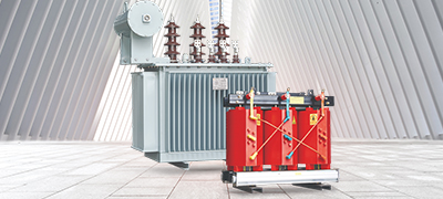
The transformer is made according to electromagnetic induction. It consists of an iron core laminated with silicon steel sheets (or silicon steel sheets) and two sets of coils wound around the iron core. The iron core and the coil are insulated from each other without any electrical connection, as shown. The coil that connects the transformer to the power supply side is called the primary coil (or the primary side), and the coil that connects the transformer to the powered device is called the secondary coil (or secondary side). When the primary coil of the transformer is connected to an AC power source, a varying magnetic field line is generated in the core. Since the secondary coil is wound on the same core, the magnetic line cuts the secondary coil, and an induced electromotive force is inevitably generated on the secondary coil, so that a voltage appears across the coil. Since the magnetic lines of force are alternating, the voltage of the secondary coil is also alternating. And the frequency is exactly the same as the power frequency.
It is proved by theory that the voltage ratio of the primary coil to the secondary coil of the transformer is related to the ratio of the turns of the primary coil to the secondary coil, which can be expressed by the following formula: primary coil voltage / secondary coil voltage = primary coil turns / secondary coil turns Explain that the more turns, the higher the voltage. Therefore, it can be seen that the secondary coil is smaller than the primary coil, which is a step-down transformer. The opposite is the step-up transformer.
3. What types of transformer design are there?
There are single-phase and three-phase transformers according to the number of phases. According to the use, there are power transformers, special power transformers, voltage regulating transformers, measuring transformers (voltage transformers, current transformers), small power transformers (for small power equipment), safety transformers, core and shell according to structure. Two. The coil has two windings and multiple windings, and the autotransformer is divided into oil immersed and air cooled by cooling.
4. What parts of the transformer components are made up of?
Transformer components are mainly composed of iron cores and coils, in addition to fuel tanks, oil pillows, insulating bushings and tappings.
5. What is the use of transformer oil?
The role of transformer oil is: (1) insulation. (2) Heat dissipation. (3) Eliminate the arc effect.
6. What is an autotransformer?
The autotransformer has only one set of coils. The secondary coil is tapped from the primary coil. Its power transmission, in addition to electromagnetic induction transmission, also has electrical transmission. The transformer silicon steel sheet and copper wire are larger than the general transformer. Less, often used to regulate voltage.
7. How is the regulator regulated?
The regulator is constructed in the same way as an autotransformer except that the core is wound into a toroidal core. The secondary coil tap uses a slidable brush contact to make the contact slide along the surface of the coil to achieve a smooth adjustment voltage.
8. What is the current relationship between the primary and secondary coils of the transformer?
When the transformer is running with a load, the change in the secondary coil current causes a corresponding change in the primary coil current. According to the principle of magnetic potential balance, the current of the primary secondary coil is inversely proportional to the number of turns of the coil. The current on the side with a large number of turns is small, and the current on the side with a small number of turns is large. It can be expressed by the following formula: primary coil current/time Stage coil current = secondary winding turns / primary winding turns.
9. What is the voltage change rate of the transformer?
The voltage change rate of the regulator is one of the main performance indicators of the transformer. When the transformer supplies power to the load, the voltage at the load end of the transformer will inevitably drop. The voltage value to be dropped is compared with the rated voltage value. The percentage, that is, the rate of voltage change, can be expressed by the formula; the voltage change rate = [(secondary rated voltage) - Load terminal voltage) / secondary rated voltage] × 100%. The normal power transformer, when connected to the rated load, has a voltage change rate of 4 to 6%.
10. How to ensure that the transformer has a rated voltage output?
Too high or too low voltage will affect the normal operation and service life of the transformer, so it must be regulated. The method of voltage regulation is to draw several taps in the primary coil, which is connected to the beginning of the tap, and the tapping of the contacts is used to change the number of turns of the coil. As long as the position of the tap-changer is turned, the required voltage rating can be obtained. It should be noted that the voltage regulation should normally be carried out after the load connected to the transformer is cut off.
11. What is the usual small transformer? Where is the application?
A small transformer is a single-phase transformer with a capacity of less than 1 kVA, and is mostly used as a power transformer for electrical equipment control, a power transformer for electronic equipment, and a power transformer for safety lighting.
12. What are the losses of the transformer during operation? How to reduce losses?
The loss in the operation of the transformer consists of two parts; (1) is caused by the iron core. When the coil is energized, the magnetic flux is alternating, causing eddy current and hysteresis loss in the iron core. This loss is collectively referred to as iron loss. (2) is caused by the resistance of the coil itself. When the primary coil and the secondary coil of the transformer pass current, power loss is generated. This loss is called copper loss.
The sum of iron loss and copper loss is transformer loss, which is related to transformer capacity, voltage and equipment utilization. Therefore, when selecting a transformer, the equipment capacity should be consistent with the actual usage as much as possible to improve the utilization of the equipment. Be careful not to make the transformer run lightly.
13. What is the nameplate of the transformer? What are the main technical data on the nameplate?
The nameplate of the transformer indicates the performance, technical specifications and usage of the transformer, which is used to meet the users choice. The main technical data that are usually selected for attention are:
(1) The kilovolt-amperes of the rated capacity. That is, the output capability of the transformer under rated conditions. Such as single-phase transformer rated capacity = U line × I line; three-phase transformer capacity = U line × I line.
(2) Rated voltage volts. Indicate the value of the terminal voltage of the primary coil and the terminal voltage of the secondary coil (when the load is not connected). Note that the terminal voltage of the three-phase transformer refers to the U line value of the line voltage.
(3) Rated current amperage. Refers to the line current I line value that the primary and secondary coils allow long-term passage under rated capacity and allowable temperature rise.
(4) Voltage ratio. Refers to the ratio of the primary coil rated voltage to the secondary coil rated voltage.
(5) Wiring method. The single-phase transformer has only one set of coils of high and low voltage, and is only used for single-phase use. The three-phase transformer has Y/△ type. In addition to the above technical data, there are transformer rated frequency, phase number, temperature rise, transformer impedance percentage and so on.
14, how to choose a transformer? How to determine the reasonable capacity of the transformer?
First of all, it is necessary to investigate the power supply voltage of the electricity place, the actual power load of the user and the conditions of the place, and then select one by one according to the technical data indicated on the nameplate of the transformer. Generally, the capacity, voltage, current and environmental conditions of the transformer should be considered comprehensively. The transformer capacity should be selected based on the capacity, nature, and time of use of the users electrical equipment to determine the amount of load required.
In normal operation, the load on the transformer should be about 75 to 90% of the rated capacity of the transformer. When the actual load of the transformer is less than 50%, the small-capacity transformer should be replaced. If it is greater than the rated capacity of the transformer, the large transformer should be replaced immediately. At the same time, in selecting the transformer to determine the primary coil voltage value of the transformer according to the line power, and selecting the voltage value of the secondary coil according to the electric equipment, it is preferably selected as the low-voltage three-phase four-wire power supply. This provides both power and lighting power.
For the choice of current, pay attention to the load can meet the requirements of the motor when the motor starts (because the motor starting current is 4 to 7 times larger than the sinking operation).
15. Why cant the transformer run at overload?
Overload operation means that the transformer exceeds the current value specified on the nameplate when it is running. The overload is divided into normal overload and accident overload. The former refers to the increase of the users power consumption under normal power supply conditions. It often causes the transformer temperature to rise, which causes the transformer insulation to age and reduce the service life. The transformer is not allowed to operate under overload. Under special circumstances, the overload operation of the transformer in a short time shall not exceed 30% of the rated load (winter) and shall not exceed 15% in summer. For the latter, the time limit for accident overload and allowable time is shown in the table below.
16. What kinds of tests should the transformer perform during operation?
In order to ensure the normal operation of the transformer, the following tests should be carried out frequently;
(1) Temperature test. Whether the operating state of the transformer is normal or not, the temperature is very important. The regulations stipulate that the upper oil temperature must not exceed 85C (ie, the temperature rises to 55C). Generally, transformers are equipped with special temperature measuring devices.
(2) Load measurement. In order to improve the utilization rate of the transformer and reduce the loss of electric energy, in the operation of the transformer, it is necessary to determine the power supply capacity that the transformer can truly bear. The measurement work is usually carried out during peak hours of each season and is directly measured with a clamp-type ammeter. The current value should be 70-80% of the rated current of the transformer. If it exceeds the load, it should be adjusted immediately.
(3) Voltage measurement. The regulations require that the voltage variation range be within ±5% of the rated voltage. If this range is exceeded, taps should be used to adjust the voltage to the specified range. The voltage of the secondary coil terminal and the terminal voltage of the end user are generally measured by a voltmeter.
(4) Measurement of insulation resistance. In order to keep the transformer in normal operation, the insulation resistance must be measured to prevent insulation aging and accidents. When measuring, try to stop the transformer. Use the shaker to measure the insulation resistance of the transformer. The required resistance is not lower than 70% of the previously measured value. When the shaker is selected, the low-voltage coil can be used at 500 volts.